
Buyer guide
Contact Assembly Welding vs Riveting
A guide to the information that defines a welded or riveted electrical contact assembly before sampling.
For teams assessing a finished contact-and-support assembly rather than an individual rivet.
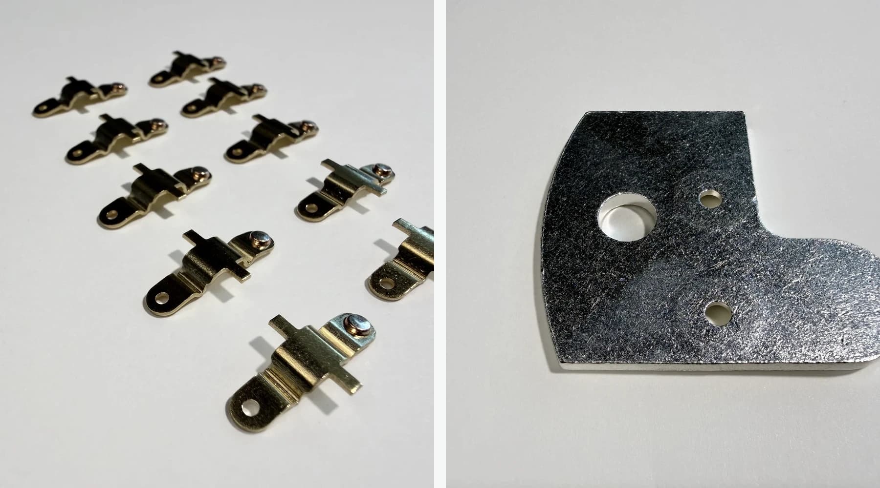
Assess the finished assembly, not only the contact
Contact assemblies combine a contact with a conductive support, position, orientation, and joining arrangement. The contact and support should therefore be evaluated as one finished unit.
The first technical question is not which joining name sounds stronger. It is whether the contact material, support material, joint position, finished geometry, and acceptance points are understood.
Riveted assemblies
A riveted contact assembly mechanically joins a contact rivet to a stamped or formed support. Check the rivet position, orientation, support geometry, surface condition, and installed function.
Support stamping or forming, contact-rivet positioning, mechanical joining, and sample inspection form one manufacturing process.
Welded and brazed assemblies
A welded contact assembly joins the contact to a conductive support at the required position. The materials, support geometry, and joint design determine the welding or brazing route.
Depending on the design, the process may use resistance spot welding, resistance brazing, induction brazing, or furnace brazing. Confirm the final route and acceptance checks for the part.
What to prepare for the first technical check
The initial discussion is more productive when the assembly relationship is visible, even if the final drawing is not complete.
- Contact and support material, or the best available material description
- Joint position, orientation, support thickness, and key locations
- Finished surface condition and any handling or packaging concern
- Whether dimensions, appearance, bonding, shear, or section checks are required
- An available drawing, physical sample, photo, application description, quantity, and timing