
Resources
What to Include in a Copper Stamped Part RFQ
Turn a drawing, sample or product photo into a useful first stamping discussion.
For purchasing and engineering teams sourcing contact blades, terminals and conductive supports.
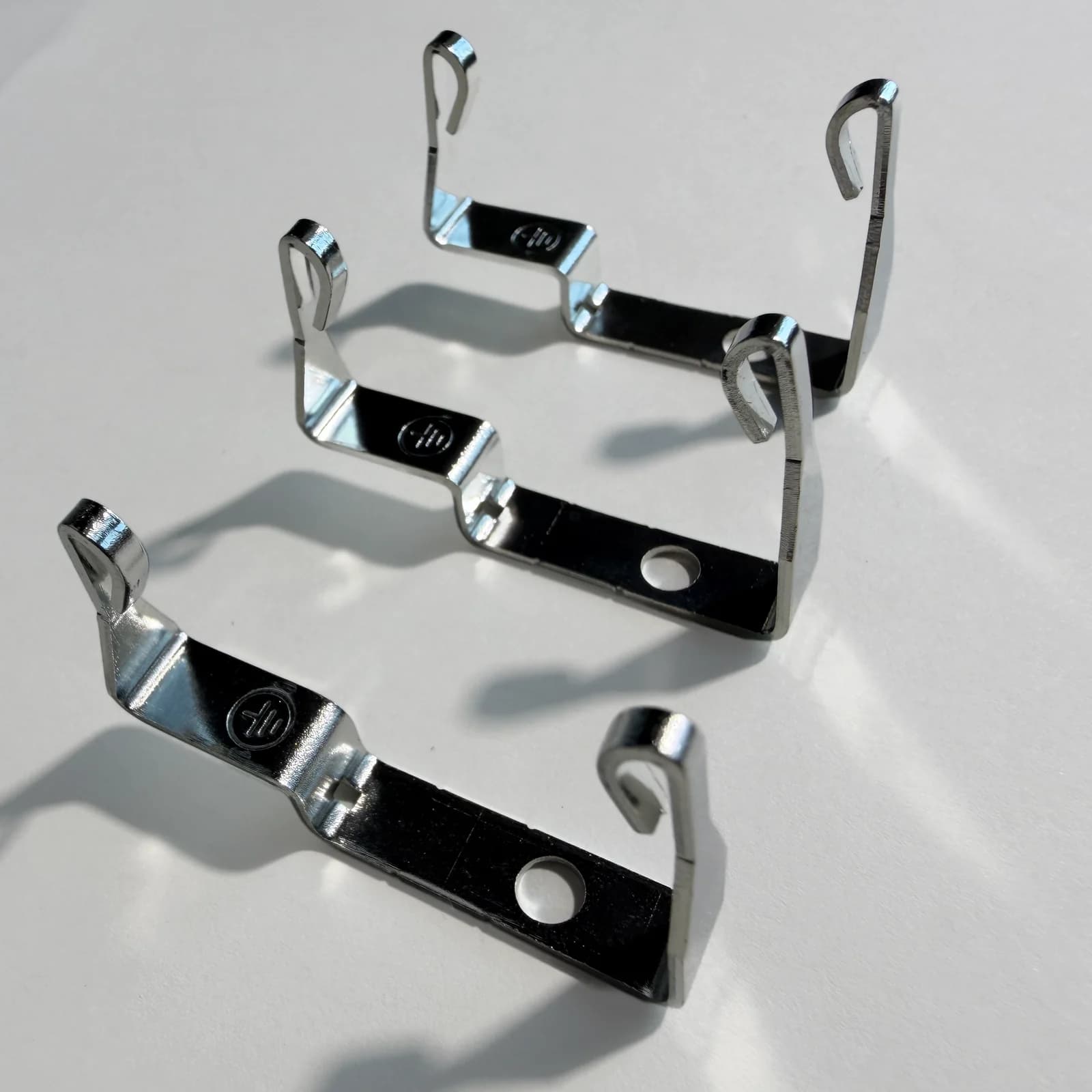
Identify the part and the features that matter
Start with the part's function and the best information already available. A drawing is useful, but a physical sample, product photograph or application description can also begin the discussion. Identify the mating surfaces, hole locations and formed features that control assembly. Mark which dimensions are functional, which are reference values and which still need confirmation.
Specify the material and finished condition
Give the full copper or copper-alloy grade when known, along with sheet thickness and the required material condition. Conductivity, strength and forming behaviour are different properties; a shorthand such as 'high-purity copper' does not replace a material specification. Describe bare copper, silver plating or another specified surface condition, and identify the relevant areas. If a silver contact feature or later joining operation is involved, show its position and requirements.
- Material grade and condition, or the existing material specification
- Sheet thickness and its acceptance requirement
- Finished surface condition and the areas affected
- Any later forming, riveting, welding or brazing operation
Show holes, bends and edge requirements together
A flat outline does not fully describe a formed part. Include the views needed to show bend direction, the finished relationship between features and the reference surfaces used for measurement. Identify the permitted burr direction or the edges that need special attention. Connect edge requirements to assembly, handling and the part's function instead of assuming every edge has the same requirement.
Show the flat and formed requirements
Features on a formed part
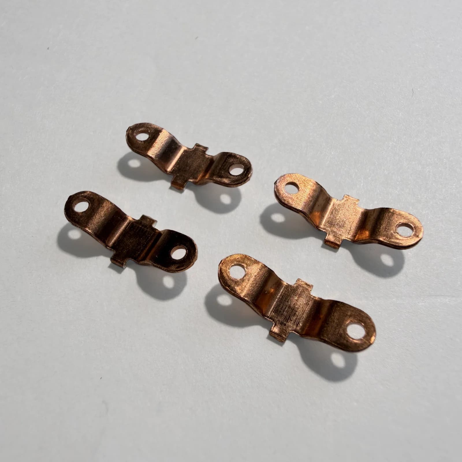
- Hole
- Formed region
- Surface or edge to specify
Locate holes, formed regions and the surfaces or edges that matter in assembly.
Flat outline · example
- Hole location and reference
- Bend line
- Edge requirement
Locate holes from a defined reference and identify the bend line and important edges.
Formed view · example
- Sheet thickness
- Finished bend geometry
- Functional locating surface
Describe sheet thickness and the finished relationship between the formed features.
The photograph shows holes and formed features on real parts. The drawing sketches show examples of the information to identify in an RFQ.
Drawings are schematic, not dimensioned representations of the photograph. Specify the material, thickness, datums, formed geometry, edge requirements and surface condition for your part.
Swipe the table horizontally to see all columns.
| Feature | Useful information |
|---|---|
| Holes and slots | Size, position and the datum or mating feature used to locate them |
| Bends | Direction, finished angle or geometry, and any specified bend radius |
| Thickness | Sheet thickness, material condition and the applicable acceptance requirement |
| Edges and burrs | Permitted direction, specified limits and the edges that matter in use |
| Surface and contact areas | Required finish, affected zones and any later joining or electrical-contact feature |
The schematic illustrates what to identify. It does not set dimensions, tolerances or tooling requirements for a particular part.
Separate sample quantity, production batch and annual demand
State how many pieces are needed for the first evaluation, the expected production batch and the likely delivery pattern. These quantities answer different questions about tooling, process choice and future orders. For stamped conductive parts, sample quantity and any tooling or development charge are assessed separately during project review. Production MOQ is generally 100 pieces per part number per order; smaller pilot quantities can be assessed for the project.
Agree what the sample must demonstrate
Explain whether the sample is intended to confirm geometry, assembly fit, surface condition or a later manufacturing step. Identify the drawing revision, key checks and any handling or packaging needs. Once the available information is sufficient, we can provide a preliminary feasibility assessment and a non-binding budgetary quote. Final production pricing follows the verified sample, process and agreed supply conditions.
Discuss Your Part
Tell us which part you need and the quantity you have in mind. You can start with a drawing, sample, photo or application description. We will review the information and outline the next step for sampling or quotation.