
Riveted Contact Assemblies
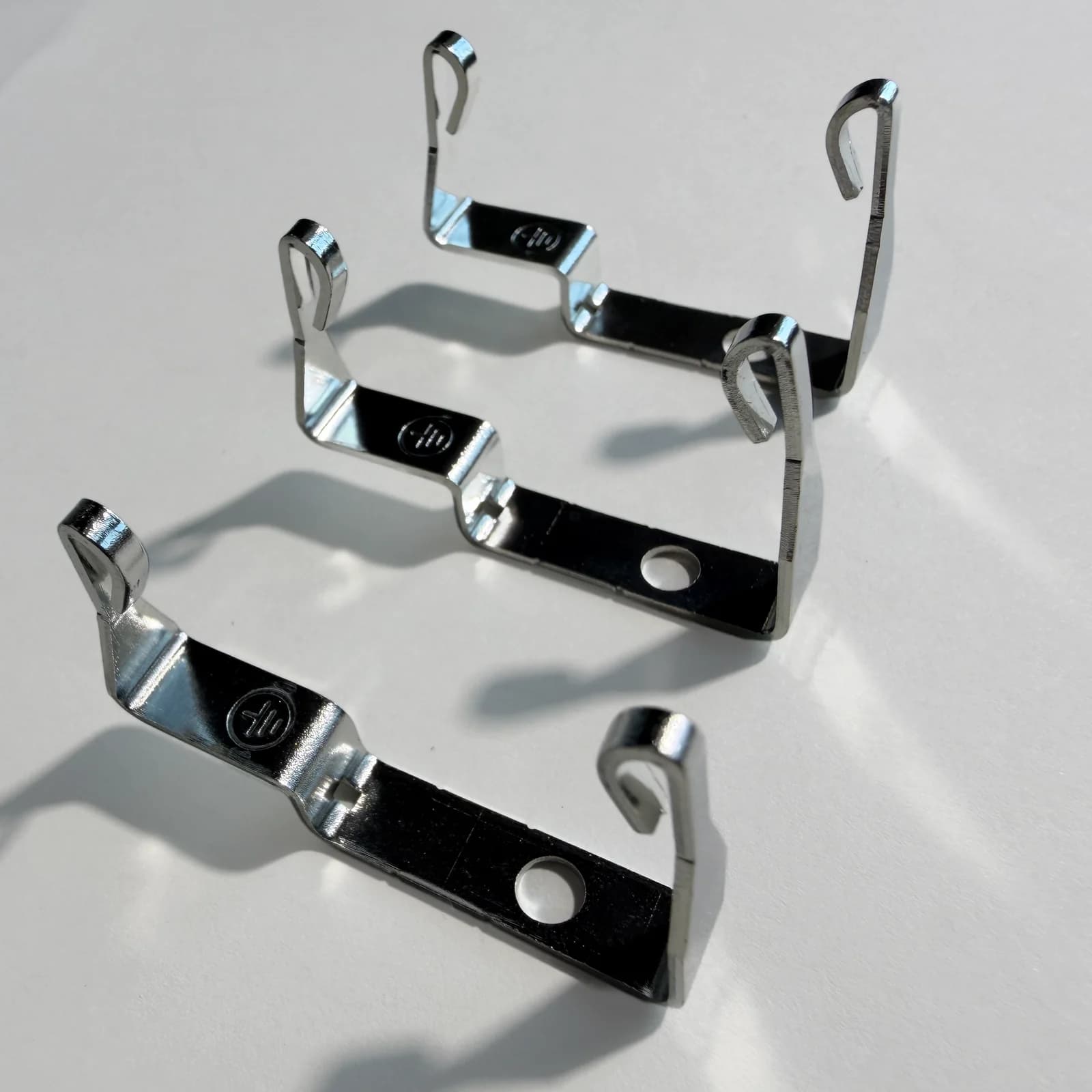
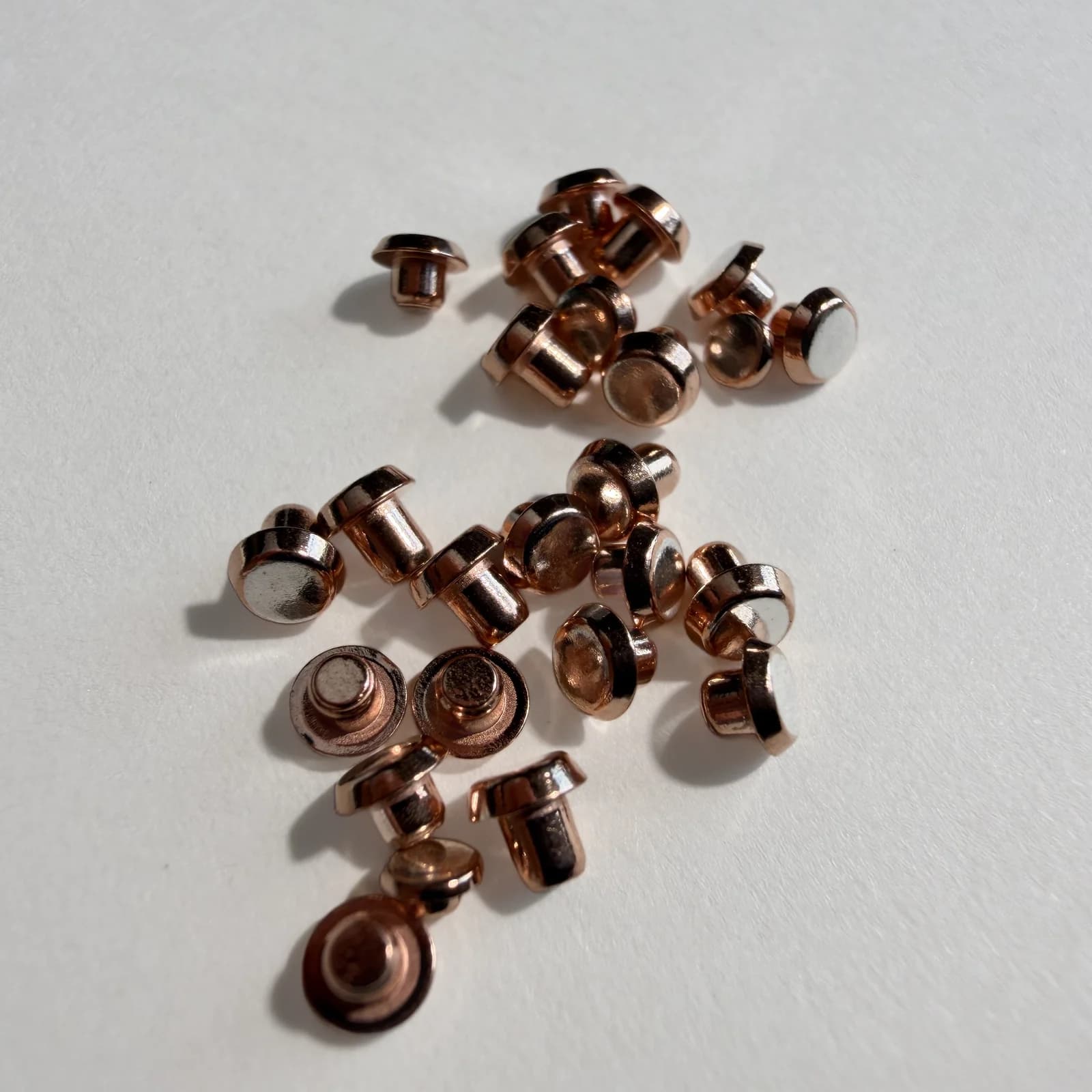
Riveted contact assemblies for relays, switches and contactors, with the contact secured to a stamped or formed conductive support.
Riveted Contact Assemblies · 1 / 2
Part details
- Type
- Riveted Contact Assemblies
- Materials
- Specified contact materials with copper or copper-alloy supports
- Applications
- Relays, switches, contactors, circuit breakers
- Reference size
- Key assembly dimensions confirmed by drawing or sample
Sampling & supply
- Sample development
- Available after technical review
- Production MOQ
- Confirmed by part, material, tooling and production arrangement; sample and trial quantities assessed separately
- Sample lead time
- Typically 5-10 working days after technical review and agreed start conditions
- Production lead time
- Typically 15-20 days after technical review and agreed start conditions
Construction and supply options.
See the complete assembly
Start from the contact, support part, and their installed relationship as one finished unit.
Align the input parts
Clarify the supplied parts, production responsibility, and required surface condition.
Set the joint arrangement
Define the rivet position, assembly orientation, and acceptance checks for the finished assembly.
Create a repeatable assembly
The approved assembly sample becomes the working specification for repeat-production checks.
Riveted assembly dimensions
Confirm the support, contact position, rivet orientation, and finished assembly dimensions together.
- Contact material and support material
- Support thickness, key locations, and overall assembly geometry
- Rivet position, orientation, and finished surface condition
- Agreed visual, joint, and assembly checks
| Dimension | How confirmed |
|---|---|
| Support thickness | Drawing or sample |
| Contact position and projection | Drawing or sample |
| Rivet position and orientation | Drawing or sample |
| Overall assembly length / width | Drawing or sample |
| Tolerances | Technical review |
Confirm these dimensions and tolerances from the drawing or sample, material system, and project review before production.
Manufacturing & Inspection
Manufacturing
Support preparation, contact positioning, and riveting are planned as one assembly process.
- Support stamping or forming as required
- Contact-rivet positioning and mechanical joining
- Assembly orientation and key-location control
- Sample production to the approved assembly sample or drawing
Inspection
Acceptance checks follow the assembled joint and its installed function.
- Key dimensions, position, and orientation
- Visual condition and finished surface
- Joint condition and shear-related checks where specified
- Cross-section or metallographic checks when required by the inspection plan
Understand the Structure and Key Features
Mechanical joint · section
The rivet passes through the support; its end is formed to retain the assembly.
- Contact head
- Conductive support
- Formed rivet end
Compare the contact material, conductive support and joining method.
Related products
Products
Sample and quote
Share the support geometry, rivet position, orientation, drawing, or sample before production. Include the drawing or sample reference, expected quantity, and required timing. With sufficient drawings or specifications, we can prepare a quotation before sampling. Any sample or process validation required for the project is agreed and completed before mass production.