
Welded Contact Assemblies
Complete welded or brazed electrical contact assemblies, combining the contact and its stamped or formed conductive carrier. Made to your drawing or sample.
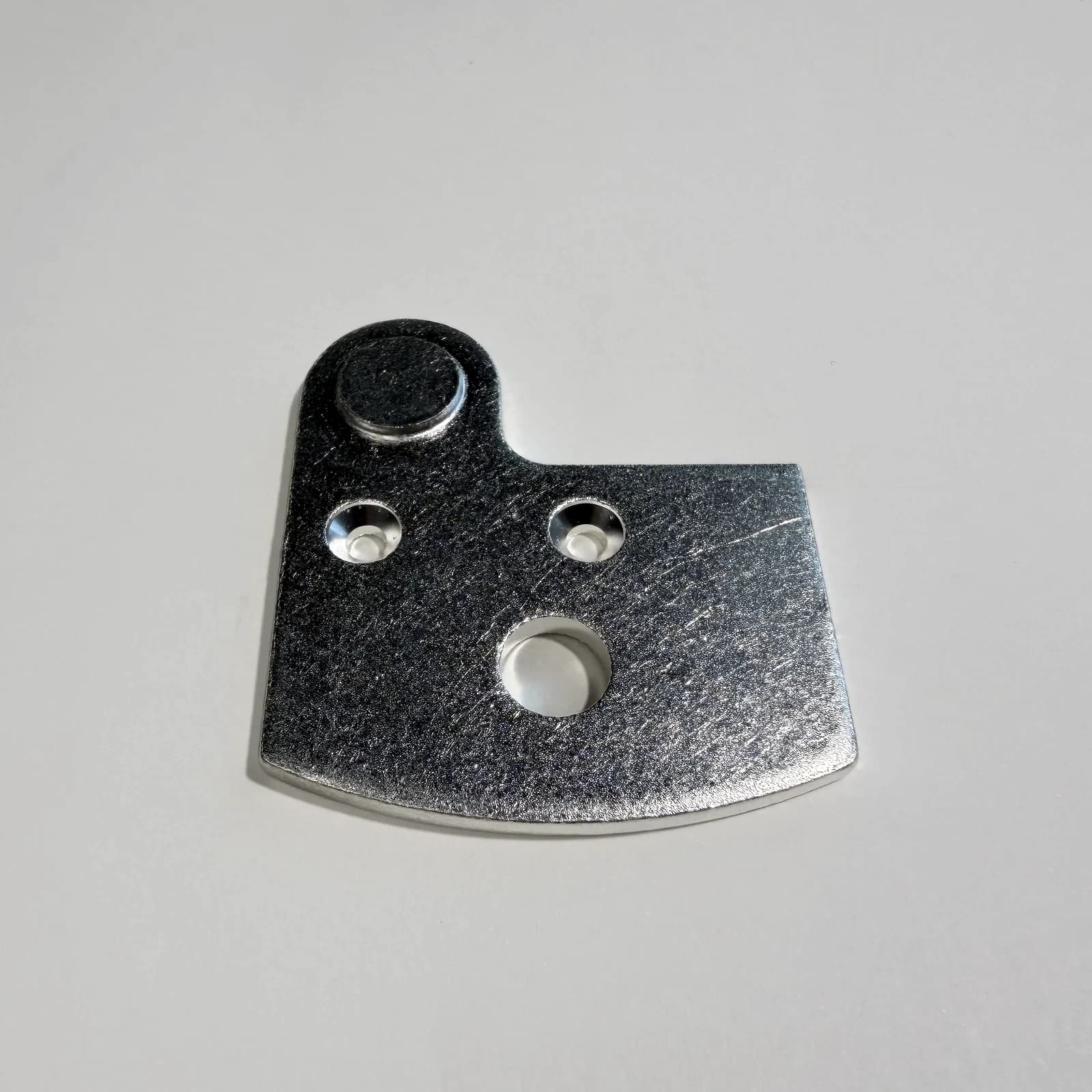
- Materials
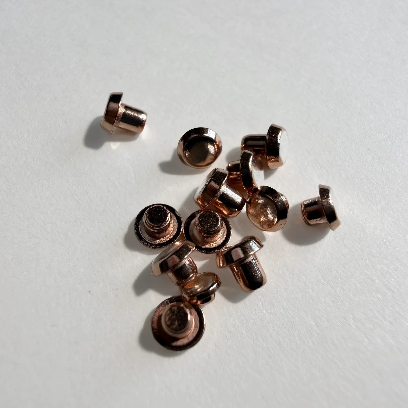
- Specified contact materials with copper or copper-alloy supports
- Applications
- Relays, switches, contactors, circuit breakers
- Reference size
- Key joint and assembly dimensions confirmed by drawing or sample
- Contact and support materials
- Confirmed from the drawing or sample
- Joint position
- Confirmed from the drawing or sample
- Assembly geometry
- Confirmed from the drawing or sample
- Inspection requirements
- Confirmed from the drawing or sample
Definition
Complete welded or brazed electrical contact assemblies, combining the contact and its stamped or formed conductive carrier. Made to your drawing or sample.
Development
Requirement clarification, drawing or sample checks, preliminary feasibility, sample development, and process verification support a final production quotation.
- Contact and carrier together: Combine the specified contact material with a copper or copper-alloy support, with the contact position and assembly geometry defined by your drawing.
- Welding and brazing options: Resistance welding and resistance, induction or furnace brazing are available where appropriate. The contact, carrier and joint design determine the manufacturing route.
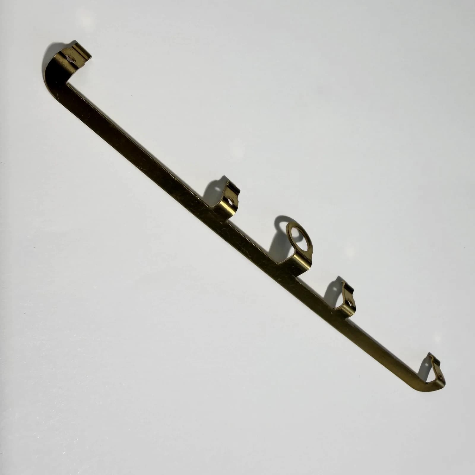
- Stamped or formed supports: Include the carrier's holes, bends and locating features in the assembly specification so the contact and support can be supplied as a finished unit.
- Checks matched to the joint: Agree the dimensional and visual checks for the finished assembly. Bonding, shear or cross-section checks are included when specified in the inspection plan.
Welded assembly dimensions
The contact material, support, joint position, and geometry determine the welding or brazing route.
- Contact and support material combination
- Joint position, orientation, and key assembly dimensions
- Welding or brazing route selected for the finished part
- Agreed visual, bond, and section checks
| Dimension | How confirmed |
|---|---|
| Support thickness | Drawing or sample |
| Contact size and position | Drawing or sample |
| Joint location and orientation | Drawing or sample |
| Overall assembly length / width | Drawing or sample |
| Tolerances | Technical review |
Confirm these dimensions and tolerances from the drawing or sample, material system, and project review before production.
Manufacturing & Inspection
Manufacturing
The joining method is selected according to the part design and the required assembly outcome.
- Resistance spot welding where applicable
- Resistance brazing, induction brazing, or furnace brazing where applicable
- Support stamping or forming as required
- Joint positioning and sampling to the approved assembly specification
Inspection
Inspection focuses on the joint, geometry, and agreed evidence for the specific assembly.
- Joint position, key dimensions, and overall appearance
- Weld or braze visual condition
- Bonding or shear checks where specified
- Cross-section or metallographic checks when required by the inspection plan
Related products
Products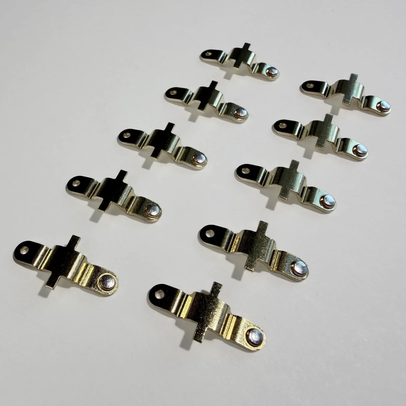
Sample and quote
Send the joint location, materials, surface condition, drawing, or sample before production. Include the drawing or sample reference, expected quantity, and required timing. Typical MOQ: 100 pcs per part number per order. Sample lead time: typically 5-10 working days after technical review and agreed start conditions. Production lead time: typically 15-25 working days after technical review and agreed start conditions.