
Bimetal Contact Rivets
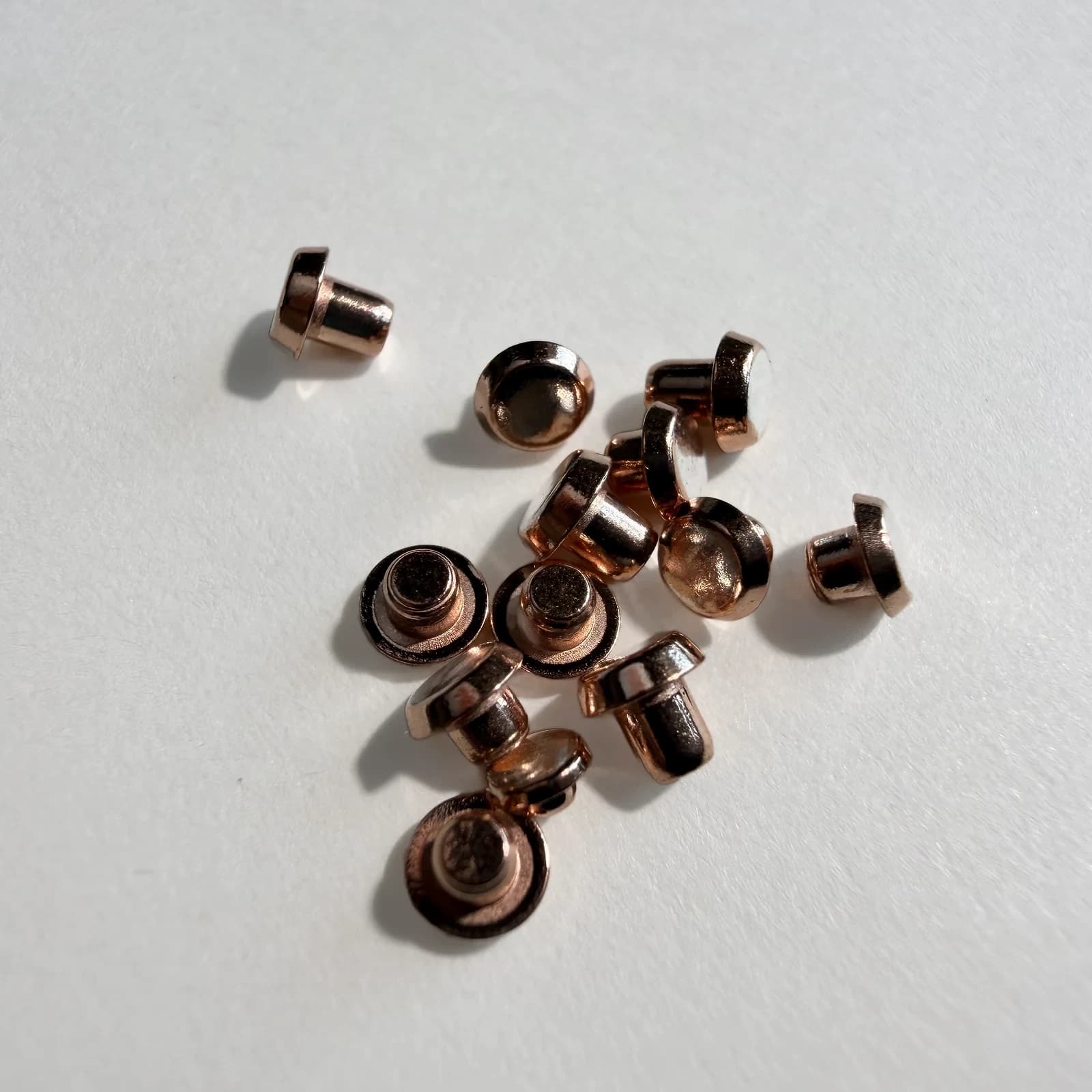
Silver and silver-alloy contact heads joined to copper shanks, supplied as custom bimetal rivets for relays, switches, contactors, and circuit breakers.
- Type
- Bimetal contact rivets
- Materials
- Ag/Cu, AgNi/Cu, AgSnO₂/Cu, and AgCdO/Cu composite systems
- Applications
- Relays, switches, contactors, circuit breakers
- Custom manufacturing
- Developed from drawings, physical samples, product photos, or application requirements
- Key dimensions
- Reference combinations from 2.5–8.0 mm head diameter; confirm final values by drawing or sample
- Sample development
- Available after technical review
- Typical MOQ
- Generally 100 pcs per part number per order; smaller pilot quantities can be assessed separately
- Sample lead time
- Typically 5-10 working days after technical review and agreed start conditions
- Production lead time
- Typically 15-25 working days after technical review and agreed start conditions
Silver contact heads with copper shanks.
Contact-material options
Ag, AgNi and AgSnO₂ contact heads can be combined with a copper base. The material system follows your application and part specification.
Head, shank and silver layer
The reference tables below cover head and shank dimensions and contact-layer combinations. Final dimensions and tolerances follow the agreed drawing or sample.
Rivets or complete assemblies
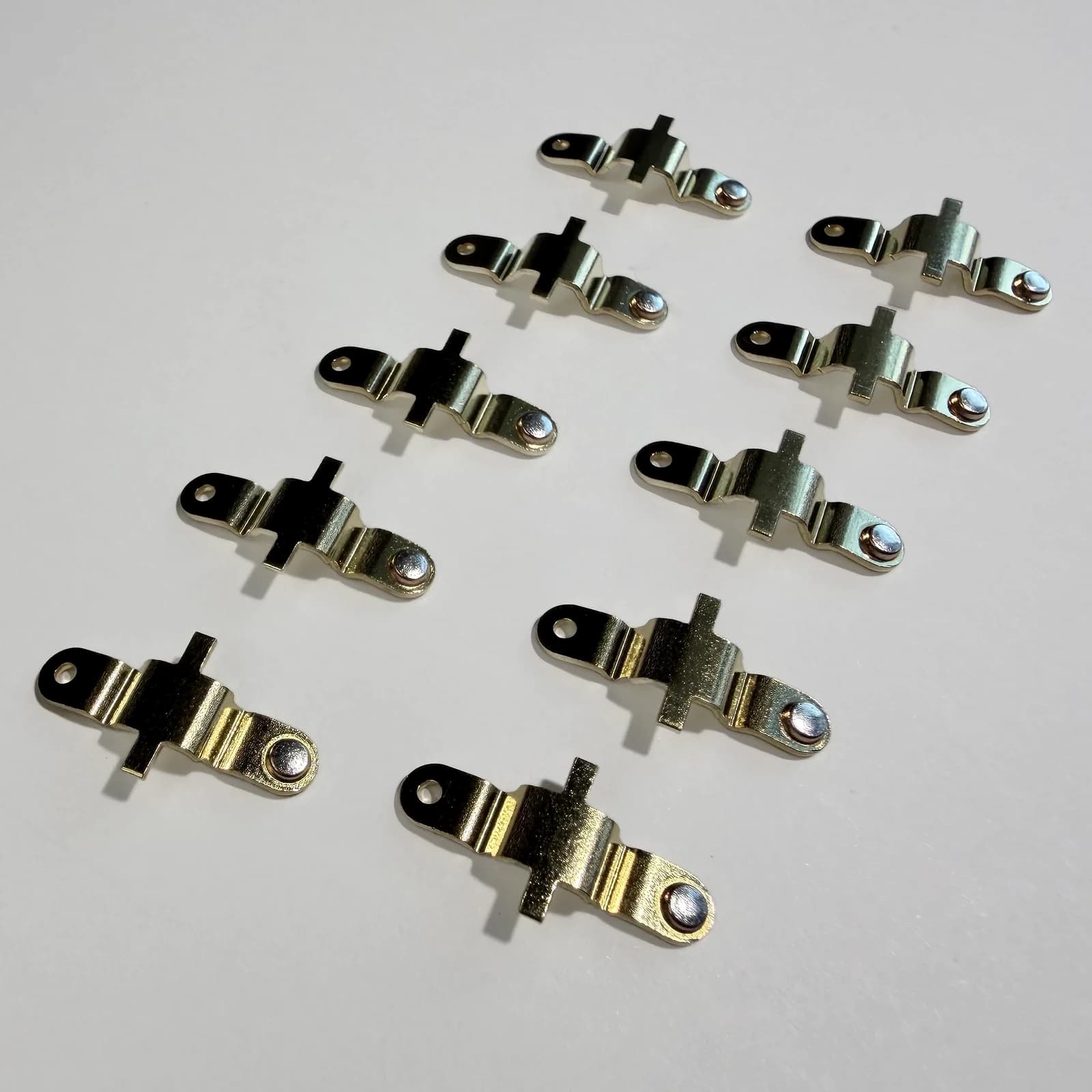
Source the individual contact rivet, or discuss a riveted contact assembly supplied with its conductive carrier.
Start with a trial part
Conventional individual contact-rivet samples and sample processing are free after technical review; international courier freight is paid by the customer. Special materials, tooling and other chargeable work are agreed before starting.
Bimetal reference size combinations
Use the reference combinations below to identify a starting point for an RFQ. Final dimensions, tolerances, material system, and process are confirmed from the drawing or sample.
| Head diameter D (mm) | Head thickness T (mm) | Contact layer thickness S (mm) | Shank diameter d (mm) | Shank length L (mm) | Spherical radius SR (mm) | Draft angle θ |
|---|---|---|---|---|---|---|
| 2.5 | 0.6, 0.8, 1.0 | 0.30–0.40 | 1.2, 1.5 | 1.0–2.0 | 4, 6 | 9° |
| 3.0 | 0.8, 1.0, 1.2 | 0.35–0.50 | 1.5 | 1.0–2.0 | 6, 8 | 9° |
| 3.5 | 0.8, 1.0, 1.2 | 0.35–0.50 | 1.5, 2.0 | 1.0–3.0 | 6, 8 | 9° |
| 4.0 | 1.0, 1.2, 1.5 | 0.35–0.50 | 2.0 | 1.0–3.0 | 8, 10 | 9° |
| 4.5 | 1.0, 1.2, 1.5 | 0.35–0.50 | 2.0, 2.5 | 1.0–3.0 | 8, 10 | 9° |
| 5.0 | 1.0, 1.2, 1.5, 2.0 | 0.40–0.60 | 2.5 | 1.0–3.0 | 10, 15 | 9° |
| 5.5 | 1.0, 1.2, 1.5, 2.0 | 0.40–0.60 | 2.5, 3.0 | 1.0–3.0 | 10, 15 | 9° |
| 6.0 | 1.0, 1.2, 1.5, 2.0 | 0.40–0.60 | 3.0 | 1.0–3.0 | 15, 20 | 9° |
| 6.5 | 1.2, 1.5, 2.0 | 0.50–0.70 | 3.0, 3.5 | 1.0–3.0 | 15, 20 | 9° |
| 7.0 | 1.2, 1.5, 2.0 | 0.50–0.70 | 3.5 | 1.0–3.0 | 20, 25 | 9° |
| 8.0 | 1.2, 1.5, 2.0 | 0.50–0.70 | 4.0 | 1.0–3.0 | 20, 25 | 9° |
Typical reference combinations for an initial RFQ. Select a compatible set; values in each row are options, not every cross-combination. Final dimensions, tolerances, material system, and process are confirmed from the drawing or sample.
| Feature | Reference tolerance |
|---|---|
| Head diameter D | ±0.10 mm |
| Head thickness T | ±0.05 mm |
| Contact layer thickness S | S ≤ 0.4: +0.06 / 0; S > 0.4: 0 / −0.06 mm |
| Shank diameter d | d < 2.0: 0 / −0.02 mm; d ≥ 2.0: 0 / −0.10 mm |
| Shank length L | +0.15 / 0 mm |
| Spherical radius SR | ±0.2R |
| Draft angle θ | 9° ± 2° |
Reference values for an initial RFQ. Confirm the applicable dimensions and tolerances from the drawing or sample, material system, and project review before production.
| Feature | Reference |
|---|---|
| Applicable condition | D ≥ 4.0 mm and S ≥ 0.3 mm |
| Boss diameter D1 | Drawing or sample |
| Boss height T1 | T1 = S − (0.15–0.25 mm) |
| Transition radius R1 | 0.10–0.20 mm |
Reference values for an initial RFQ. Confirm the applicable dimensions and tolerances from the drawing or sample, material system, and project review before production.
- Confirm the final dimension combination, material system, and tolerances before production.
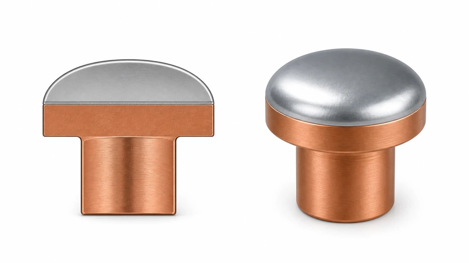
Bimetal rivet structure
A silver or silver-alloy contact head is bonded to a copper base and cylindrical shank. Use the table above for reference dimensions.
- Silver or silver-alloy contact head
- Copper base and shank
Manufacturing & inspection
Manufacturing route
We select the contact material, copper shank, forming method, and finished surface as one manufacturing route.
- Contact-head and shank material matching
- Composite rivet forming to the approved geometry
- Surface condition selected for the finished part
- Sample production to the approved drawing or sample
Inspection focus
Inspection follows the approved part construction and requirements.
- Key dimensions and visual condition
- Silver-layer assessment where specified
- Bimetal bonding check where specified
- Sample-to-production consistency against the approved sample and specification
Materials & applications
Material systems
- Silver and silver-alloy contact heads
- Copper or specified base-shank materials
- Ag/Cu, AgNi/Cu, AgSnO₂/Cu, AgCdO/Cu, and customer-specified composite systems
Typical applications
- Relays
- Switches
- Contactors
- Circuit breakers
Related technical data
Check the material data before selecting the material and manufacturing process.
Related buyer guides
Compare product types and prepare the drawing, sample, or photo for a technical check.
Confirm the head, shank, and contact layer before sampling.
Send a drawing, sample, or photo so we can confirm layer thickness, shank geometry, and assembly features.
- 01Check the application and available drawing, sample, or photo.
- 02Discuss a preliminary feasibility assessment and non-binding budgetary quote when the available information is sufficient.
- 03Develop and verify the sample and process.
- 04Confirm the final production quote and proceed after written approval.
Related product families
View all products
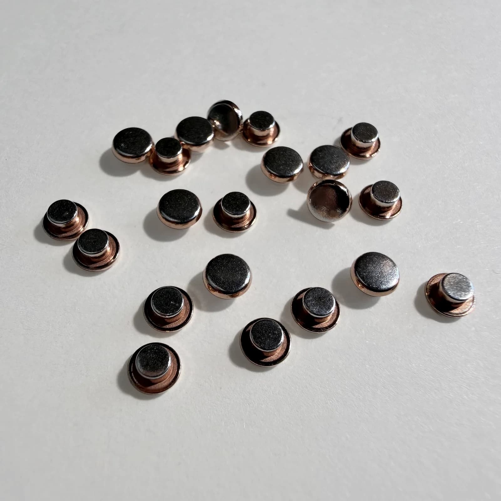
Need a bimetal rivet matched to an existing part?
Send a drawing, sample, or photo to confirm materials and dimensions.