
Bimetal Contact Rivets
Silver and silver-alloy contact heads joined to copper shanks, supplied as custom bimetal rivets for relays, switches, contactors, and circuit breakers.
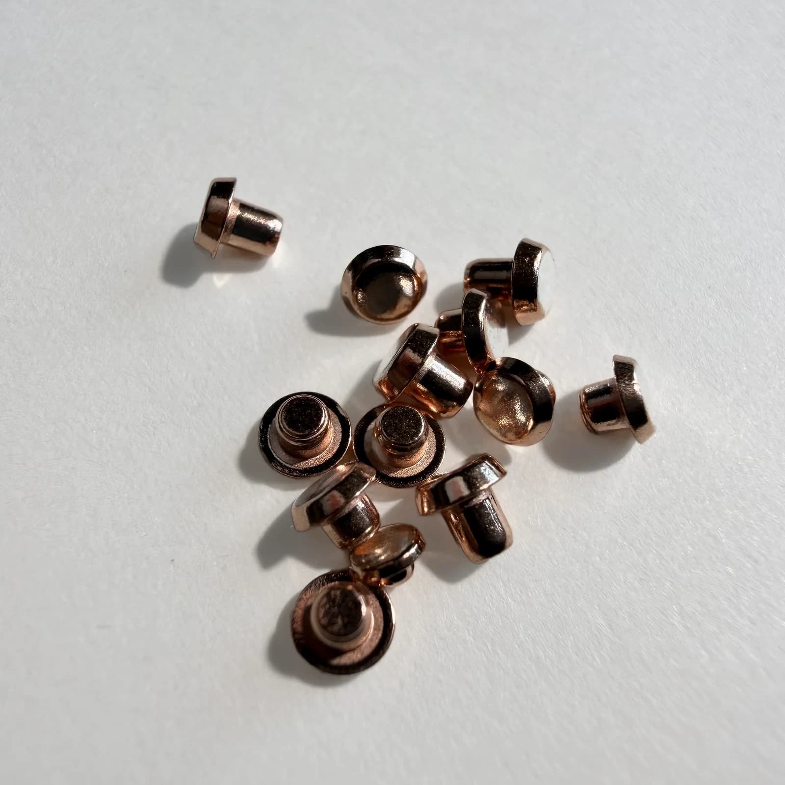
- Materials
- Ag/Cu, AgNi/Cu, AgSnO₂/Cu, and AgCdO/Cu composite systems
- Applications
- Relays, switches, contactors, circuit breakers
- Reference size
- Reference combinations from 2.5–8.0 mm head diameter; confirm final values by drawing or sample
- Contact material
- Confirmed from the drawing or sample
- Head and shank geometry
- Confirmed from the drawing or sample
- Base material
- Confirmed from the drawing or sample
- Inspection requirements
- Confirmed from the drawing or sample
Definition
Silver and silver-alloy contact heads joined to copper shanks, supplied as custom bimetal rivets for relays, switches, contactors, and circuit breakers.
Development
Requirement clarification, drawing or sample checks, preliminary feasibility, sample development, and process verification support a final production quotation.
- Contact-material options: Ag, AgNi and AgSnO₂ contact heads can be combined with a copper base. The material system follows your application and part specification.
- Head, shank and silver layer: The reference tables below cover head and shank dimensions and contact-layer combinations. Final dimensions and tolerances follow the agreed drawing or sample.
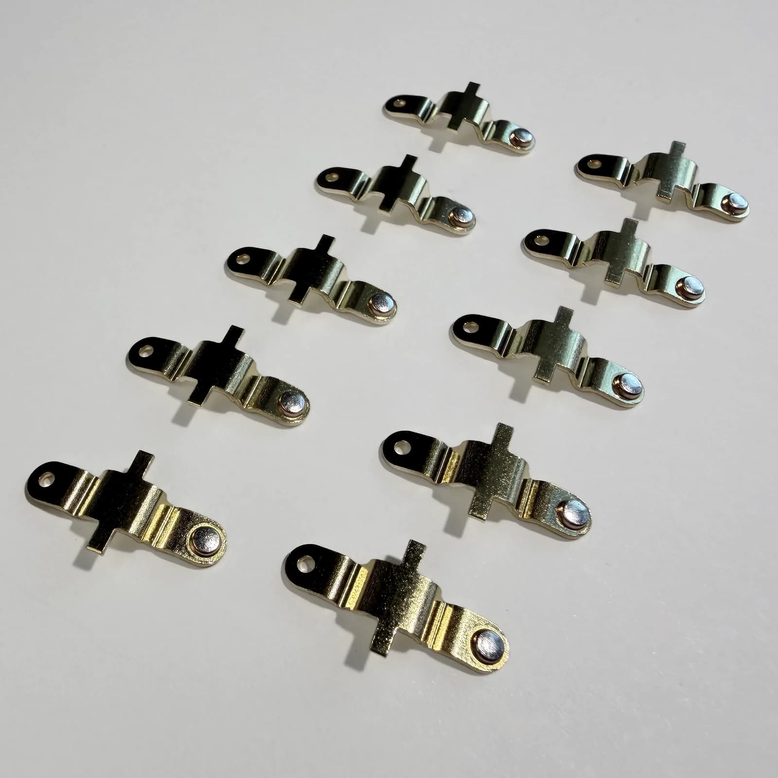
- Rivets or complete assemblies: Source the individual contact rivet, or discuss a riveted contact assembly supplied with its conductive carrier.
- Start with a trial part: Conventional individual contact-rivet samples and sample processing are free after technical review; international courier freight is paid by the customer. Special materials, tooling and other chargeable work are agreed before starting.
Bimetal reference size combinations
Use the reference combinations below to identify a starting point for an RFQ. Final dimensions, tolerances, material system, and process are confirmed from the drawing or sample.
- Confirm the final dimension combination, material system, and tolerances before production.
| Head diameter D (mm) | Head thickness T (mm) | Contact layer thickness S (mm) | Shank diameter d (mm) | Shank length L (mm) | Spherical radius SR (mm) | Draft angle θ |
|---|---|---|---|---|---|---|
| 2.5 | 0.6, 0.8, 1.0 | 0.30–0.40 | 1.2, 1.5 | 1.0–2.0 | 4, 6 | 9° |
| 3.0 | 0.8, 1.0, 1.2 | 0.35–0.50 | 1.5 | 1.0–2.0 | 6, 8 | 9° |
| 3.5 | 0.8, 1.0, 1.2 | 0.35–0.50 | 1.5, 2.0 | 1.0–3.0 | 6, 8 | 9° |
| 4.0 | 1.0, 1.2, 1.5 | 0.35–0.50 | 2.0 | 1.0–3.0 | 8, 10 | 9° |
| 4.5 | 1.0, 1.2, 1.5 | 0.35–0.50 | 2.0, 2.5 | 1.0–3.0 | 8, 10 | 9° |
| 5.0 | 1.0, 1.2, 1.5, 2.0 | 0.40–0.60 | 2.5 | 1.0–3.0 | 10, 15 | 9° |
| 5.5 | 1.0, 1.2, 1.5, 2.0 | 0.40–0.60 | 2.5, 3.0 | 1.0–3.0 | 10, 15 | 9° |
| 6.0 | 1.0, 1.2, 1.5, 2.0 | 0.40–0.60 | 3.0 | 1.0–3.0 | 15, 20 | 9° |
| 6.5 | 1.2, 1.5, 2.0 | 0.50–0.70 | 3.0, 3.5 | 1.0–3.0 | 15, 20 | 9° |
| 7.0 | 1.2, 1.5, 2.0 | 0.50–0.70 | 3.5 | 1.0–3.0 | 20, 25 | 9° |
| 8.0 | 1.2, 1.5, 2.0 | 0.50–0.70 | 4.0 | 1.0–3.0 | 20, 25 | 9° |
Typical reference combinations for an initial RFQ. Select a compatible set; values in each row are options, not every cross-combination. Final dimensions, tolerances, material system, and process are confirmed from the drawing or sample.
| Feature | Reference tolerance |
|---|---|
| Head diameter D | ±0.10 mm |
| Head thickness T | ±0.05 mm |
| Contact layer thickness S | S ≤ 0.4: +0.06 / 0; S > 0.4: 0 / −0.06 mm |
| Shank diameter d | d < 2.0: 0 / −0.02 mm; d ≥ 2.0: 0 / −0.10 mm |
| Shank length L | +0.15 / 0 mm |
| Spherical radius SR | ±0.2R |
| Draft angle θ | 9° ± 2° |
Reference values for an initial RFQ. Confirm the applicable dimensions and tolerances from the drawing or sample, material system, and project review before production.
| Feature | Reference |
|---|---|
| Applicable condition | D ≥ 4.0 mm and S ≥ 0.3 mm |
| Boss diameter D1 | Drawing or sample |
| Boss height T1 | T1 = S − (0.15–0.25 mm) |
| Transition radius R1 | 0.10–0.20 mm |
Reference values for an initial RFQ. Confirm the applicable dimensions and tolerances from the drawing or sample, material system, and project review before production.
Manufacturing & Inspection
Manufacturing
We select the contact material, copper shank, forming method, and finished surface as one manufacturing route.
- Contact-head and shank material matching
- Composite rivet forming to the approved geometry
- Surface condition selected for the finished part
- Sample production to the approved drawing or sample
Inspection
Inspection follows the approved part construction and requirements.
- Key dimensions and visual condition
- Silver-layer assessment where specified
- Bimetal bonding check where specified
- Sample-to-production consistency against the approved sample and specification
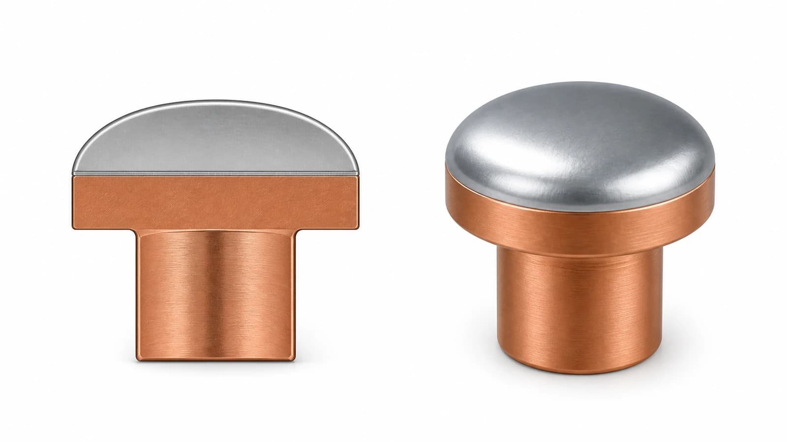
Bimetal rivet structure
A silver or silver-alloy contact head is bonded to a copper base and cylindrical shank. Use the table above for reference dimensions.
- Silver or silver-alloy contact head
- Copper base and shank
Related products
Products
Sample and quote
Send a drawing, sample, or photo so we can confirm layer thickness, shank geometry, and assembly features. Include the drawing or sample reference, expected quantity, and required timing. Typical MOQ: 100 pcs per part number per order. Sample lead time: typically 5-10 working days after technical review and agreed start conditions. Production lead time: typically 15-25 working days after technical review and agreed start conditions.