
Trimetal Contact Rivets
A three-part contact rivet for designs that need a contact layer on more than one face or at the shank end.
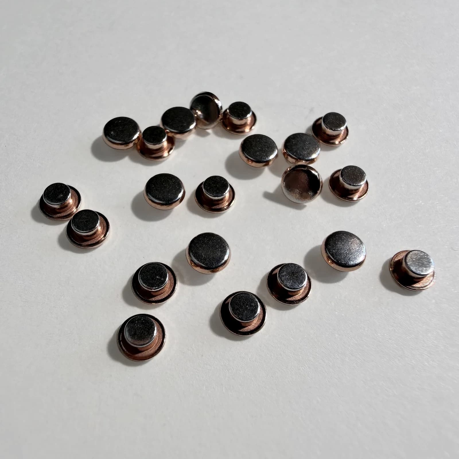
- Type
- Trimetal contact rivets
- Materials
- Silver-alloy / copper-based three-part material systems
- Applications
- Relays, switches, contactors, circuit breakers
- Custom manufacturing
- Developed from drawings, physical samples, product photos, or application requirements
- Key dimensions
- Type A/B indicative ranges; confirm final dimensions by drawing or sample
- Sample development
- Available after technical review
- Typical MOQ
- Generally 100 pcs per part number per order; smaller pilot quantities can be assessed separately
- Sample lead time
- Typically 5-10 working days after technical review and agreed start conditions
- Production lead time
- Typically 15-25 working days after technical review and agreed start conditions
Choose the Type A or Type B layer arrangement.
Understand the layer arrangement
Use the available part and application information to clarify where each contact layer is needed.
Plan the material system
Define the contact layer, intermediate material, and base for the intended assembly.
Bring material and geometry together
Consider material use, geometry, tooling, and forming as one manufacturing process.
Confirm the production plan
The verified sample and process support the final production quote and control plan.
Type A and Type B dimensions
Type A and Type B use different layer arrangements, so their dimensions are listed separately.
| Type | D (mm) | T (mm) | S1 (mm) | S2 (mm) | d (mm) | L (mm) | SR (mm) | Draft angle |
|---|---|---|---|---|---|---|---|---|
| A1 | 3.5–4.0 | 0.8–1.1 | 0.35–0.50 | 0.30–0.50 | 2.0 | 1.5–2.5 | 6–12 | 11° |
| A2 | 4.0–5.0 | 0.9–1.3 | 0.40–0.70 | 0.8–1.0 | 2.5 | 1.5–3.5 | 8–15 | 11° |
| B1 | 2.5–3.5 | 0.4–0.9 | 0.20–0.35 | 0.30–0.50 | 1.8–2.2 | 0.8–1.5 | 6–12 | 13° |
| B2 | 3.0–4.0 | 0.6–1.1 | 0.25–0.50 | 0.30–0.60 | 2.4–2.7 | 0.9–1.8 | 8–15 | 13° |
| B3 | 4.0–4.5 | 0.7–1.2 | 0.30–0.55 | 0.30–0.60 | 2.9–3.2 | 1.0–2.0 | 10–20 | 13° |
| B4 | 4.5–5.5 | 0.8–1.5 | 0.30–0.60 | 0.40–0.70 | 3.5–4.5 | 1.5–2.5 | 10–30 | 13° |
Reference dimensions only. Final dimensions and tolerances are confirmed from the drawing or sample, material system, and project review.
Manufacturing & inspection
Manufacturing route
Layer arrangement, material selection, geometry, tooling, and process feasibility are considered together before sampling.
- Three-part layer arrangement for the required contact faces
- Material and geometry review before production sampling
- Forming route selected for the approved type A or type B structure
- Finished surface condition selected for the part and application
Inspection focus
Inspection follows the required layer position and approved specification.
- Key dimensions and visual condition
- Head and foot silver-layer assessment where specified
- Trimetal bonding condition where specified
- Sample-to-production consistency against the approved sample and specification
Materials & applications
Material systems
- Silver and silver-alloy contact layers
- Copper-based intermediate and shank structures
- AgNi, AgSnO2, AgCdO, and customer-specified material systems
Typical applications
- Relays
- Switches
- Contactors
- Circuit breakers
Related technical data
Check the material data before selecting the material and manufacturing process.
Related buyer guides
Compare product types and prepare the drawing, sample, or photo for a technical check.
Confirm the layer stack before tooling and sampling.
Provide the layer arrangement, geometry, drawing, or sample so we can define the material and forming route.
- 01Check the application and available drawing, sample, or photo.
- 02Discuss a preliminary feasibility assessment and non-binding budgetary quote when the available information is sufficient.
- 03Develop and verify the sample and process.
- 04Confirm the final production quote and proceed after written approval.
Related product families
View all products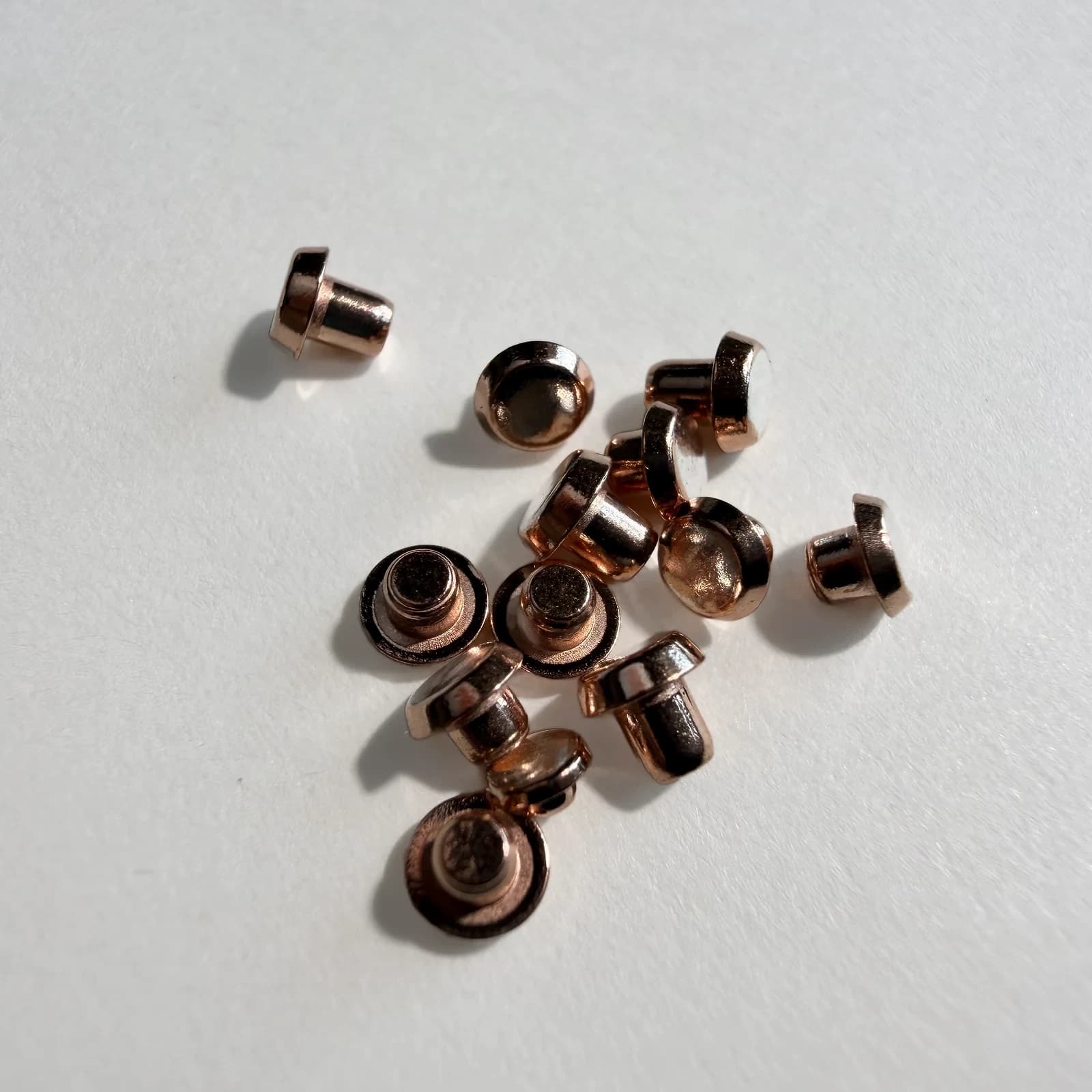
Need contact material on more than one face or at the shank end?
Send the layer arrangement, drawing, sample, or photo for assessment.